
What is the actual process of configuring a high availability pair of NetScaler SD-WAN SE appliances, what needs to be configured on the secondary appliance in order for the high availability to form?
This is a question I have been asked a number of times so I thought I would put together my answers.
The documentation is good with regard to initial setup but what actually happens once these instructions have been followed.
Note: High availability Appliances MUST be the same and have the same license.
Below is my setup using XenServer and VPX and the process of creation of the high availability pair.
Firstly, ensure that a network interface is available for the high availability heartbeat. (I explain later about heartbeat interfaces later)
Here’s a screen shot from my XenServer environment — added internal network to be dedicated to the high availability network interface:

This network is then bound to the VPXs that you wish to form the high availability

The high availability configuration requires a Virtual Interface to be allocated for the high availability heartbeat.
Existing Interfaces can be used but if you have spare NIC’s on your appliance it would be recommended to use one of those keeping the high availability heartbeat away from any other traffic.
In my configuration, as shown above, I have added a separate network in my XenServer for the high availability traffic seen on my VPX as interface 5.
Note: Losing high availability heartbeat can cause significant service interruption
https://docs.citrix.com/en-us/netscaler-sd-wan/9-3/ha-deployment-modes.html
- When the high availability connection between the appliances fails, both appliances go into Active state and cause a service interruption. This can be mitigated by assigning multiple high availability connections so that there is no single point of failure
Create an Interface Group for the high availability.

Allocate a virtual IP to the Interface Group – this IP can be any IP as this HA network is none routable dedicated to the two devices.

This high availability virtual interface can then be used in the high availability configuration section, as described in the docs and shown below. Another two IPs are added for the primary and secondary appliances on the same subnet as the virtual IP given when creating the Interface Group.

The secondary appliance:
- Needs to be powered up and connected onto the network as appropriate to the deployment.
- Management IP defined
- Connected to the primary appliance over the defined high availability NIC.
Now that the configuration is complete follow the standard procedure through the change management. Safe Config > Export to Change Management > stage appliances
Below screen shot of the MCN before staging appliance.
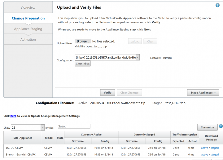
Select stage appliances and during this process please note that a package is created for the “New High Availability Appliance”

On completion download the staged package for the new DC high availability device.
Using local change management on the secondary appliance import this new configuration.
After the secondary appliance has completed the change management process and activated the HA pair will sync as seen in the screen shots below.
Dashboard on MCN before change management completes on the secondary appliance

Dashboard on MCN after change management on secondary appliance has completed; the secondary appliance is now seen and is in standby mode.

Screen shot from SD-WAN Centre inventory manager show the secondary appliance.

Now, we have a successful high availability configuration!
As shown, other than powering up the secondary appliance and connecting it to the network, there is little else to be done.